Weld inspection

About Weld Inspection

A multidisciplinary task

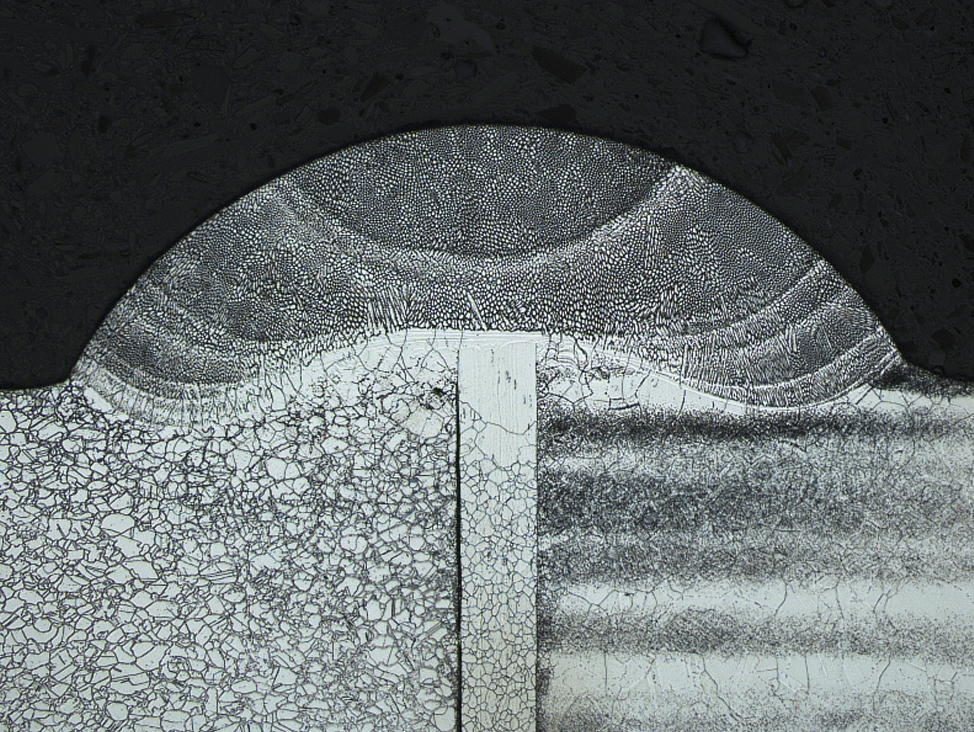
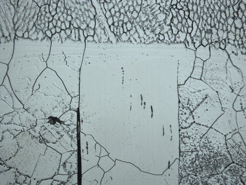
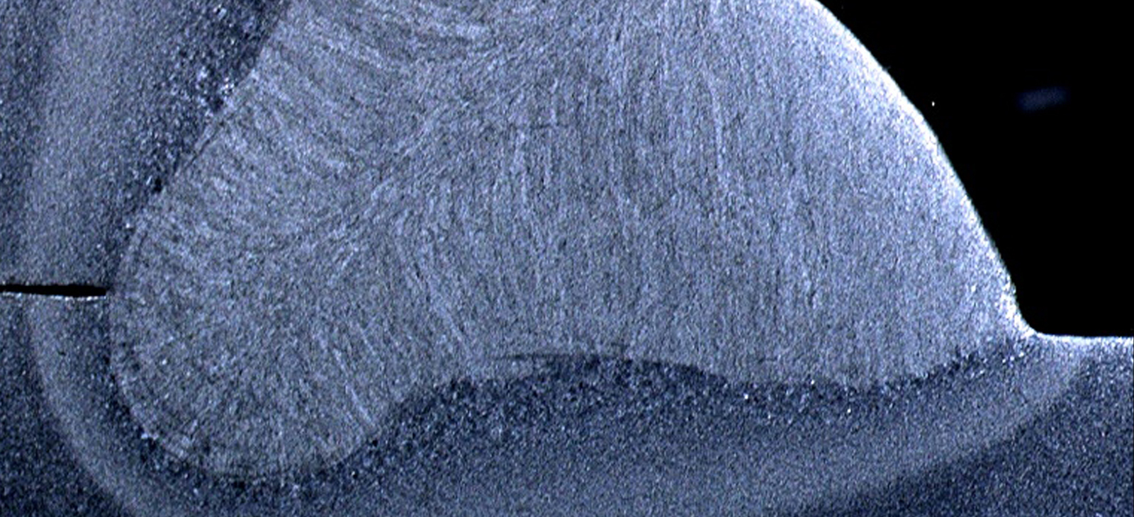
Weld inspection is a multidisciplinary task, covering many different techniques and purposes. In this section, examination of cut out sections for geometric features, hardness, or microstructure is described.

Download the application note about welds

Two levels of inspection

The examination of materialographic sections of welded joints is commonly carried out at two levels of inspection:

Weld inspection macro

Macro:

Where Magnifications up to 50 Times Are Employed with Stereomicroscopes
Macro examination is commonly carried out on unmounted cross sections through welded joints, and involves cutting and coarse/fine grinding techniques. The resultant finish is adequate for etching, followed by an examination of the macro features of the weld joint. Some of them are listed below:

  • Weld geometry
  • Number and size of passes
  • Depth of penetration
  • Extent of HAZ (heat affected zone)
  • Surface imperfections such as cracks, undercut, excessive throat, convexity, and weld toe angle
  • Internal imperfections such as cracks, porosity, metallic inclusions, lack of fusion, lack of penetration, and slag
  • Joint geometry imperfections such as root gap, root face, angle of chamfer, and misalignment

Weld inspection micro

Micro:

Where Examination Is at Higher Magnifications (up to 1,000 Times) Using Optical Microscopes
For micro examination techniques and hardness traverse, the provision of a polished, optically flat surface will be required. Micro examination is carried out for studies of weld imperfections and micro structural features such as:

  • Voids (porosities, shrinkage cavities, micro-cracks)
  • Special phases (sigma-phase in stainless steel)
  • Grain sizes/structure
  • Weld structure
  • Segregation
  • HAZ and base structure

How to Do Weld Inspection

In general, conventional materialographic and hardness testing techniques also apply to weld sections. However, the characteristics of welds introduce some specific challenges for the materialographic preparation.


Cutting

Often, flame cutting is used as a primary cutting technique to remove a more manageable welded section from a larger fabrication. In this case, it is important that the macro/micro section is cut by an abrasive wet cutting process and is sectioned well away from the influence of any thermal damage from a primary thermal cutting operation.

In order to minimize the deformation from cutting and the risk of thermal damage on the cut surface, general suggestions for the selection of cutoff wheel and cutting parameters apply.

Mounting
Normally, macro sections for procedural testing are prepared unmounted because of time constraints, and because a finely ground finish is usually adequate for macro examination. If semi-automatic preparation is an option, then there are a number of specimen holders which will accommodate unmounted cross sections from welded joints.

If mounting is required, then there is the option of hot compression mounting or cold mounting. It is not uncommon, however, in weld examination to have relatively large cross sections. In this case, rectangular molds for cold mounting can be used.

Mechanical Preparation
Traditionally, welded sections for macro examination are prepared manually on successively finer grades of silicon carbide paper to a 1,200 grit finish. For larger samples or long grinding times, a resin-bonded diamond disk can offer some advantages in terms of lifetime and constant removal rate.

For micro examination and hardness traverse, the preparation requirements also include polishing.

Weld specimens can involve wide variations in material hardness across the specimen, either because of a phase changes during welding, or because the joint incorporates dissimilar metals. The weld metal may contain hard precipitates or some indigenous weld defect. Therefore, it is important that the preparation method should ensure that polish relief between microstructural features is minimal, and all microstructural elements are retained. In this respect, semiautomatic or automatic preparation equipment is preferred, as it provides a consistency and reproducibility of polish which facilitates accurate microstructural analysis.


Etching
Both chemical and electrolytic etching can be utilized, depending on the alloy and the analysis required. The most common etchant used for carbon and low alloy steel is Nital of varying concentrations; alternatively, a ten percent ammonium persulphate may be used. For difficult alloys, such as stainless steels and nickel alloys, one should consider electrolytic etching. Electrolytic etching offers some advantages over chemical etching solutions, such as speed, ease of operation, and increased safety, due to minimizing user contact with the etchants.

For applications where detailed microstructural analysis is required, the specimens for electrolytic polishing and etching should be ground to 1,000 grit.


Geometric Features

The geometric features for a weld are typically specified individually for each weld or group of welds. Therefore, failure analysis, approval, or control of a weld is, in most cases, done against a detailed specification. The type, number, and size of internal or surface imperfections are also well defined for a weld quality.

Measuring, counting, indicating, and reporting geometric features and imperfections in welds are because of the high degree of standardization, as a task can be optimized by the use of dedicated imaging systems.
GogP Consumables

Looking for consumables?

Order your consumables directly from our e-Shop.

Go to consumables in e-shop

Contact us!

icon-arrow