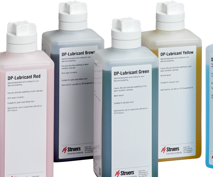
Oxide Polishing

About Grinding and Polishing

Mechanical Preparation

Mechanical preparation is the most common method of preparing materialographic specimens for microscopic examination. The specific requirement of the prepared surface is determined by the particular type of analysis or examination. Specimens can be prepared to the perfect finish, the true structure, or the preparation can be stopped when the surface is acceptable for a specific examination.

Read more

Preparation goals

Regardless of the preparation requirements, the overall goals of the preparation are the same:


  • All structural elements must be retained.
  • The surface must be without scratches or deformation.
  • No foreign matter may be introduced on the specimen's surface.
  • The specimen must be plane and highly reflective.
  • The optimal price per sample should be obtained.
  • All preparations must be 100% reproducible.

The basic process of mechanical specimen preparation is material removal, using abrasive particles in successively finer steps to remove material from the surface until the required result is achieved.

There are three mechanisms for removing material: grinding, polishing, and lapping. They differ in the tendency to introduce deformation in the specimen's surface.

How to grind and polish

The goal of materialographic specimen preparation is to reveal the true structure of the specimen, whether it is metal, ceramic, sintered carbide, or any other solid material.

The easiest way to accomplish this is with a systematic preparation method. When the work routinely involves examining the same material, in the same condition, achieving the same result each time is desirable. This means that the preparation result must be reproducible.

Sample preparation follows certain rules which are valid for most materials. Different materials with corresponding properties (hardness and ductility) respond similarly and require the same consumables during preparation. Therefore, all the materials can be displayed in the Metalogram according to their properties, and not because they belong to a certain material group.

Case story: Preparation time reduces from 60 to 11 minutes

How to select a preparation method

The Metalogram displays materials according to specific physical properties: hardness and ductility. 

  • Hardness: The easiest attribute to measure but is not sufficient information about a material to find the correct preparation method.
  • Ductility: The ability of a material to deform plastically is important for grinding and polishing. This property expresses how the material responds to mechanical abrasion.

The X-axis represents the hardness in Vickers (HV). The values are not shown in a linear progression, because the variety of preparation methods for softer materials is greater than for hard ones. The shape of the Metalogram results from soft materials generally being more ductile and hard materials usually being more brittle.

Metalogram

Selection of a Preparation Method

1. Find the hardness on the X-axis.

2. Move up or down, depending on the ductility of the material. Unlike hardness, ductility is not easily defined in precise numbers.

3. Place the material on the Y-axis according to any previous experience. A prerequisite is to have an idea of how a ductile or brittle material will perform.

METALOGRAM METHODS

The Metalogram is based on ten preparation methods. Seven methods, A - G, cover the complete range of materials. They are designed to produce specimens with the best possible results. In addition, three short methods, X, Y, and Z, are displayed. These methods are for very quick, acceptable results.

Some materials such as composites, coatings, or other materials consisting of various phases or components cannot be easily placed in the Metalogram. In these cases, the following rules can be applied when deciding on the preparation method:

  • Predominant component Select a method which is suited for the material's predominant component.
  • Artifacts Check the samples after each step and, if preparation artifacts do occur, consult troubleshooting for advice. The most common artifacts are edge rounding, relief, pull-outs, and porosity.
Metalog Method A

Metalogram area (A)

MgAl alloy, cast. Mag: 500x; Etchant: Molybdic acid
Example number 1

Metalog Method B

Metalogram area (B)

Cu, pure Mag: 50x, Etchant: Copper ammonium chloride
Example number  2

Metalog Method C

Metalogram area (C)

Medium carbon steel, overheated. Mag: 200x, Etchant: Nital
Example number 4

Metalog Method D

Metalogram area (D)

Low carbon steel. Mag: 100x ; Etchant: Klemm I
Example number 5

Metalog Method E

Metalogram area (E)

White cast iron. Mag: 500x ; Etchant: Klemm I
Example number 7

Metalog Method F

Metalogram area (F)

WC/Co sintered carbide Mag: 1,000x; Filter DiC
Example number 8

Metalog Method G

Metalogram area (G)

ZrO2. Mag: 200x
Example number 10

Metalog Method X

Metalogram area (X)

AlSi alloy Mag: 100x
Example number 3

Metalog Method Z

Metalogram area (Y)

Tool steel Mag: 200x, Etchant: Nital
Example number 6

Method Z

Metalogram area (Z)

Carbides in metallic matrix Mag 200x
Example number 9

Preparation Parameters

Preparation methods present a balanced set of parameters for a grinding and polishing procedure described by the headlines below.

Surface

Surface

Surfaces are carefully selected according to relevant equipment in use, sample material, and requirements for preparation. Within each group of surfaces: grinding stones, grinding or polishing paper, disks or cloth, the difference in characteristics include type of abrasive bond, abrasive type, hardness, resilience, surface pattern, and projections of fibers.

Grain size

Grit/Grain Size

The preparation is always started with the smallest possible grain size to avoid excessive damage to the specimens. During the subsequent preparation steps, the largest possible intervals from one grain size to the next are chosen in order to minimize preparation time.

Abrasive

The removal rate in grinding and polishing is closely related to the abrasives used. Diamonds are one of the hardest known materials, as they have a hardness of approximately 8,000 HV. That means it can easily cut through all materials and phases. Different types of diamonds are available. Tests have shown that the high material removal, together with a shallow scratch depth, is obtained because of the many small cutting edges of polycrystalline diamonds. Silicon carbide, SIC, with a hardness of about 2,500 HV, is a widely used abrasive for grinding papers for mainly non-ferrous metals. Aluminium oxide, with a hardness of about 2,000 HV, is primarily used as an abrasive in grinding stones. It is mainly used for the preparation of ferrous metals. It was also extensively used as a polishing medium, but since the introduction of diamond products for this purpose, it has largely lost its usefulness in this application. Colloidal silica is used to produce a scratch-free finish in oxide polishing steps In general, the abrasive must have a hardness of 2.5 to 3.0 times the hardness of the material to be prepared. Never change to softer abrasives - this might lead to preparation artifacts. The amount of abrasive applied depends on the grinding/polishing surface and the hardness of the specimen. The combination of cloths with low resilience and hard specimens requires a larger amount of abrasive than cloths with high resilience and softer specimens, because the abrasive particles wear faster.

Lubricant

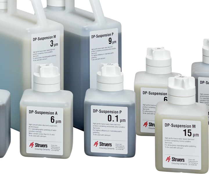
Depending on the type of material and the preparation stage, different lubricants combine levels of lubricating and cooling levels and liquid characteristics.

This may include thin lubricants with high cooling and low lubrication effect, special lubricants for polishing of soft and ductile materials, alcohol-based or water-based, etc.

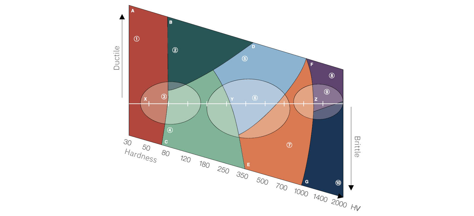
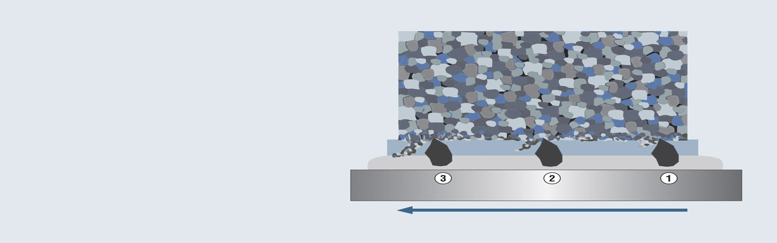
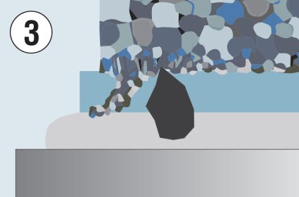
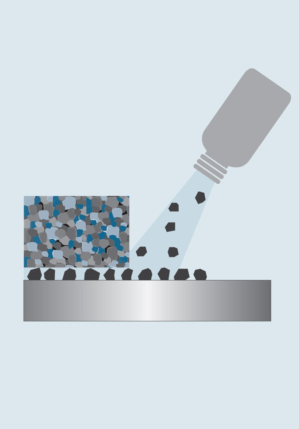
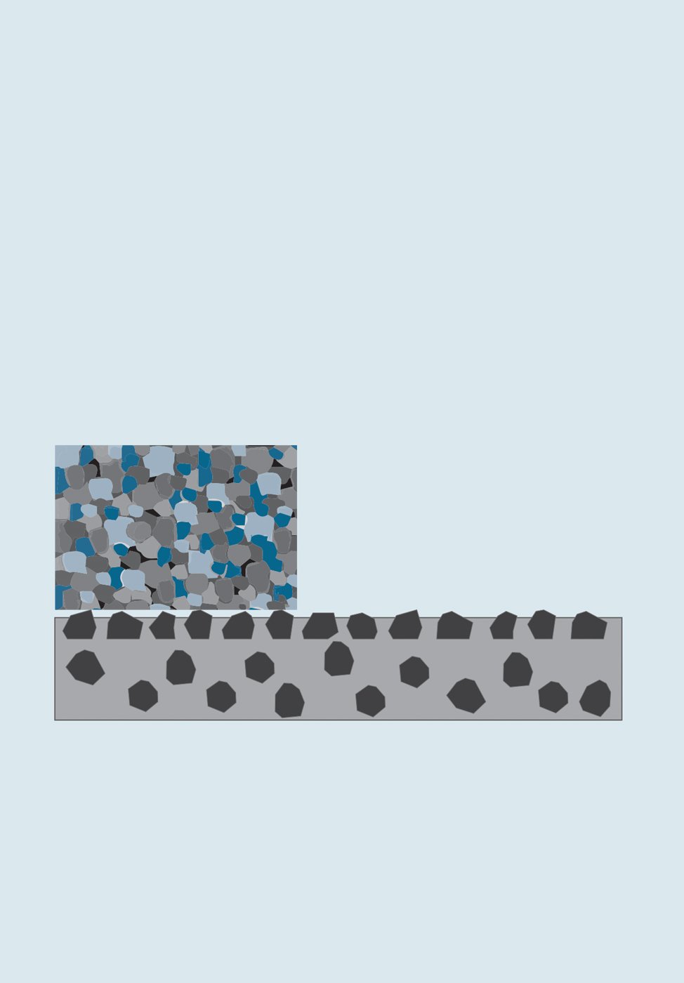
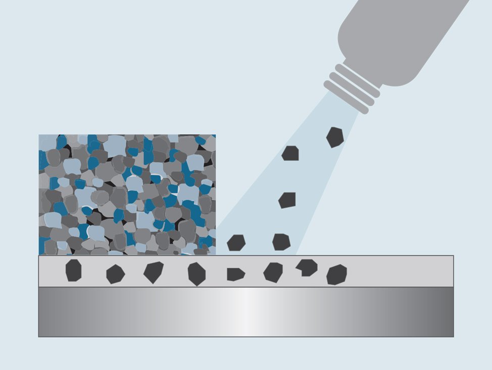
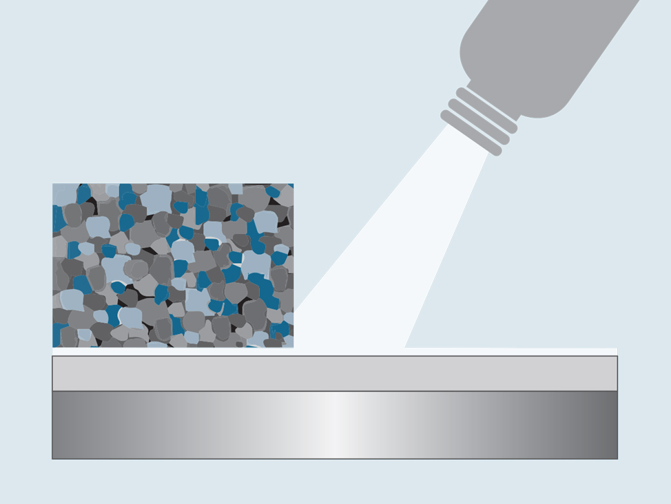
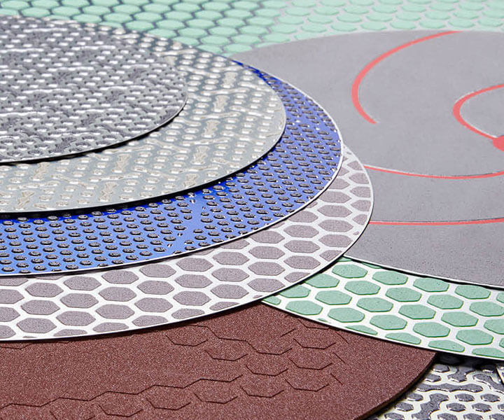
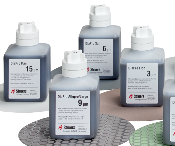
Depending on the type of material and the grinding/polishing disk used for preparation, the amounts of lubrication and cooling have to be balanced. Generally, it can be said that soft materials require high amounts of lubricant to avoid damage, but only small amounts of abrasive as there is very little wear on the abrasive. Hard materials require less lubricant but higher amounts of abrasive, due to faster wear. The amount of lubricant has to be adjusted correctly to get the best result.

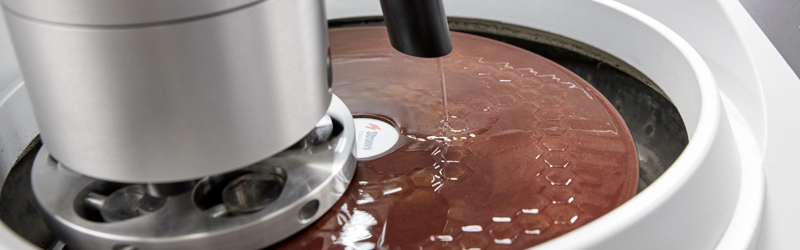
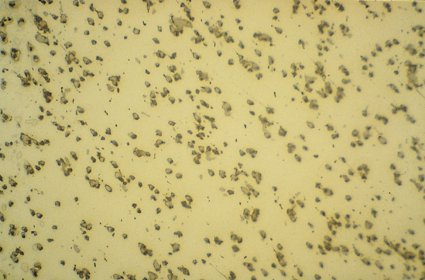
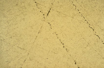
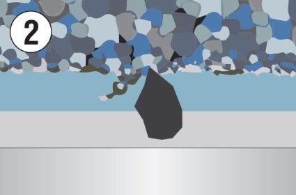
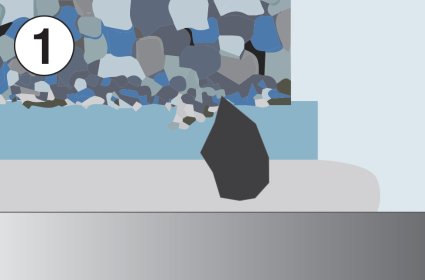
The polishing cloth should be moist, not wet. Excess lubricant will flush the abrasive from the disk and remain as a thick layer between the specimen and disk, thus reducing material removal to a minimum.

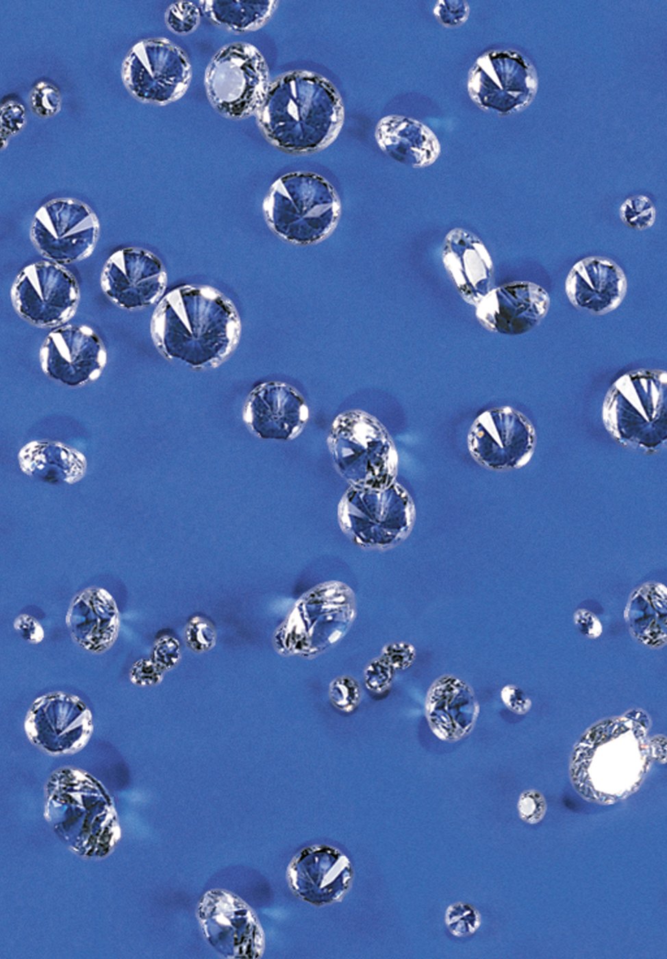
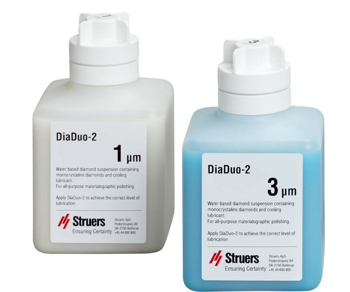
For two-in-one diamond suspensions, lubrication and cooling liquids are included and balanced in the bottle to optimize the relevant preparation method.

Rotational Speed

For PG, a high disk speed is used to get a fast material removal. For FG, DP, and OP, speeds of 150 rpm are used for both grinding/polishing disks and specimen holders. They are also both turning in the same direction. When working with loose abrasives, high speeds would throw the suspension from the disk, thus requiring higher amounts of both abrasive and lubricant.

Force

The force is expressed in Newton. The figures stated in the preparation methods are typically standardized for six specimens of 30 mm diameter, clamped in a specimen holder. The specimens are mounted, and the specimen area should be approximately 50% of the mount. If the specimens are smaller, or there are fewer specimens in a holder, the force has to be reduced to avoid damage, such as deformations. For larger specimens, the force only needs to be slightly increased. Instead, the preparation time shall be extended. Higher forces increase the temperature because of higher friction, so thermal damage may occur.

Time

Preparation time is the time during which the specimen holder is rotating and pressed against the grinding/polishing disk. The preparation time is stated in minutes. It should be kept as short as possible to avoid artifacts such as relief or edge rounding. Depending on the specimen size, the time may have to be adjusted. For larger specimens, the time shall be extended. With specimens smaller than the standard, the time is kept constant and the force reduced.

Troubleshooting - Grinding and Polishing

There Are a Few Basic Rules Which Should Always Be Followed:

  • To improve the preparation of a particular material, make sure that it has been prepared according to a suitable method from the  Metalogram.
  • If the material is being prepared for the first time, it is important to examine the specimen after every step with a microscope. This makes it easier to see when preparation artifacts occur.
  • Before proceeding to the next step, be sure that all damage from the previous step, such as scratches, pull-outs, or embedded grains, are removed completely. If this is not done, artifacts from an early step might show up on the finished surface, in which case it would be impossible to be sure where they originated. It must be known when artifacts begin to occur to be able to improve the method.
  • Keep preparation times as short as possible. Unnecessarily long preparation times waste consumables and may even damage the specimen, by causing edge rounding, comet tails, and relief, for example.
  • New polishing cloths or grinding disks may need to be "run in" for a short time, or dressed or cleaned before use, to give the best results.

Case story: How Uddeholm AB learned to troubleshoot halfmoon-shaped scratches after grinding

15 Costly Grinding and Polishing Troubles – How to Avoid Them

Scratches, smearing, staining and deformation are just a few of the troubles you want to avoid when grinding and polishing for materialographic analysis. Don’t miss these important tips to avoid the 15 most common grinding and polishing troubles.

1. TROUBLESHOOTING - Scratches 

  • Scratches are grooves in the surface of a sample, produced by the points of abrasive particles.
  • Make sure that after PG the surface of all samples in the specimen holder shows the same uniform scratch-pattern over the whole surface.
  • Repeat PG if necessary.
  • To avoid contamination of the grinding/polishing surface through large abrasive particles from a previous step, clean the samples and sample holder carefully after every step.
  •  If there are still scratches left over from the previous step after finishing the current step, increase the preparation time by 25% to 50% as a first measure. If that does not help, use the expert system.

Look at the examples and expert system as follows:

Scratches after FG

After FG, scratches from PG are still visible. Mag: 200x

Scratches after diamond polishing

After diamond polishing, scratches from FG still remain. The very deep vertical scratch might even be left over from PG. Mag: 200x

Problem

After FG, there are still scratches left from PG.
Show More
Question:
Is the MD-Allegro or MD-Largo dirty?

Explanation:
If you cannot see the pattern on the MD-Allegro or MD-Largo, it needs to be cleaned. Repeat the step.
Question:
Is the dosing of abrasive correct?

Explanation:
Adjust dosing, clean the nozzles if necessary. Repeat the step.
Question:
Is the dosing of lubricant correct?

Explanation:
Adjust dosing, clean the nozzles if necessary. Repeat the step.
Question:
Is the MD-Allegro or MD-Largo worn?

Explanation:
Check the MD-Allegro or MD-Largo. If the hexagons in the center are worn, the disk has to be replaced. Repeat the step.
There are scratches visible which are not typical for the step just carried out.
Show More
Question:
Did you use a new polishing cloth for this step?

Explanation:
New cloths must be used for several minutes before producing the optimum result. Check the dosing of the abrasive and the lubricant. Repeat the step.
Question:
Is the polishing cloth contaminated?

Explanation:
Clean or exchange the cloth. Repeat the step.
Question:
Are the samples porous, or is there a gap between the resin and the sample?

Explanation:
Clean the samples in an ultrasonic cleaner, re-impregnate under vacuum using Epofix. Start all over.
Question:
Is the dosing of lubricant and abrsive correct?

Explanation:
No: Adjust dosing, clean the nozzle if necessary. Repeat the step.

Yes: Exchange the polishing cloth. Repeat the step.

2. TROUBLESHOOTING - Smearing

The plastic deformation of larger sample areas is called smearing. Instead of being cut away or removed, material is pushed across the surface. Smearing occurs because of an incorrect application of abrasive, lubricant, polishing cloth, or a combination of these, which makes the abrasive act as if it was blunt. There are three ways to avoid smearing:

  • Lubricant: Check the amount of lubricant and, if necessary, increase it as smearing often occurs when the lubricant level is too low.
  • Polishing cloth: Due to high resilience of the cloth, the abrasive can be pressed deep into the cloth and it cannot cut. Change to a cloth with lower resilience.
  • Abrasive: The diamond grain size might be too small, which means the particles cannot cut. Use a larger grain size.

Look at the examples and expert system as follows:

Smearing on soft and ductile steel

1. Smearing on soft, ductile steel. Mag: 15x, DIC

Smearing on soft and ductile steel

2. Smearing on soft, ductile steel. Mag: 25x, DIC

Problem

If your sample is similar to figs. 1+2, you have smearing.
Show More
Question:
Check the amount of lubricant. Is the amount correct?

Explanation:
Adjust the amount of lubricant so that the polishing cloth is moist, not wet. Repeat the step.
Question:
If the amount of lubricant is correct, you can either use larger diamond sizes, or a polishing surface with lower resilence.

Explanation:
Use the next higher diamond grain size on the same type of polishing surface. Repeat the step.

3. TROUBLESHOOTING - Staining

  • Staining is often seen after cleaning or etching specimens.
  • When there is a gap between the sample and resin, water or alcohol or etchant can bleed out.
  • Areas on the specimen surface can be discoloured and make the examination difficult or even impossible.
  • Clean and dry specimens immediately after each preparation step.
  • Avoid the use of compressed air when drying your specimens after final polishing, because compressed air can contain oil or water.
  • OP polishing can result in a white film left on the specimen surface if the cleaning is not carried out correctly.

If your polisher is not equipped with automatic water flushing after the oxide polishing step during the last ten seconds of OP polishing, flush the polishing cloth with water to clean both the specimens and the cloth.

  • Do not use hot water for cleaning specimens, because hot water is more aggressive than cold water and subsequent etching will be intensified.
  • Never leave specimens in normal room conditions because humidity might attack the specimen. Always store specimens in a desiccator if you want to keep them.


Look at the example as follows:

Staining of the sample due to a gap between the resin and the sample.

Staining of the specimen due to a gap between the resin and the sample. Mag: 20x

4. Troubleshooting - Deformation

There are two types of deformation: elastic and plastic. Elastic deformation disappears when the applied load is removed. Plastic deformation, which may also be referred to as cold work, can result in subsurface defects after grinding, lapping, or polishing. Remaining plastic deformation can first be seen after etching.

Only deformation introduced during the preparation is covered here. All other types from previous operations like bending, drawing, and stretching are not considered, because they cannot be changed or improved by changing the preparation method.

  • Deformations are artifacts which first show up after etching (chemical, physical, or also optical etching).
  •  If a supposed deformation line also is visible in brightfield in unetched condition, please see the scratches section on how to improve the preparation method first.

Look at the examples and expert system as follows:

deformation

1. Short deformation lines, restricted to single grains.Mag: 100x, DIC

deformation

2. Well defined, sharp deformation lines. Mag: 200x, DIC

deformation

3. Blunt deformation lines, interrupted Mag: 500x, polarized light

Problem

After etching, deformation resulting from the preparation can be seen.
Show More
Question:
Are the deformations short lines, restricted to a single or a few grains?

Example
There seems to be only a limited amount of deformation left. Repeat the last step and adjust the preparation time accordingly.
Question:
Are the deformations long, well-defined lines, covering several grains or even the whole sample?

Example
It seems to be a recently introduced deformation. Check and clean your polishing cloth for possible dirt particles. Repeat the preparation from DP1.
Question:
Are the deformations long, blunt lines, covering several grains, maybe with interruptions?

Example
That seems to be deformation from a very early stage, e.g. PG. Repeat the preparation from FG; see also under "scratches" how to improve the preparation method.

5. Troubleshooting - edge rounding

Using a polishing surface with high resilience will result in material removal from both the sample surface and the sides. The effect of this is edge rounding and can be seen with mounted specimens if the resin wears at a higher rate than the sample material. Please check your samples after each step to see when the fault occurs so you can determine what changes you will need to make in the preparation.

Look at the examples and expert system as follows:

Edge rounding

1. Due to a gap between the resin and the sample, the edge is rounded. Stainless steel Mag: 500x, Etchant: Beraha I

Edge rounding

2. Good edge retention, stainless steel. Mag: 500x, Etchant: Beraha I

Problem

The edge retention is not acceptable. Compare with figs. 1+2.
Show More
Question:
Are your samples mounted?

Explanation:
For maximum edge retention, mounting is required. Mount your samples; start all over again.
Question:
Did you use the correct mounting resin and technique (there is no gap between the sample and the resin)?

Explanation:
There must be good adhesion between the sample and the resin. Re-mount your samples; start all over again.
Question:
Did rounding of the edges first occur during diamond polishing?

Explanation:
All materials should be fine ground using MD-Allegro or MD-Largo for maximum edge retention. Change the preparation so that MD-Allegro or MD-Largo is used for FG. Start all over again.
Question:
Did you use short polishing times?

Explanation:
Reduce polishing times as much as possible. Check samples every minute to monitor the polishing result and edge retention. Repeat the preparation from FG.
Question:
Did you use relatively low forces?

Explanation:
Normally, lower forces result in less edge rounding. For a start, reduce the force by about ten percent. Repeat the preparation from FG.
Question:
Are you using red lubricant?

Explanation:
No. On polishing cloths with high resilience, such as MD-Mol or MD-Nap, the use of green or blue lubricant can result in relief. Change to red lubricant at the present step. Repeat the preparation from FG.

Yes. Replace the polishing cloth with one of lower resilience. Repeat the preparation from FG.

6. Troubleshooting - relief

Material from different phases is removed at different rates due to varying hardness or wear rate of the individual phases. 

Relief is usually not noted until polishing begins, so it is important to begin the preparation with grinding media that will keep the samples as flat as possible. However, for the best possible starting conditions, MD-Largo should be used for fine grinding of materials with a hardness below 150 HV, and MD-Allegro should be used for fine grinding of materials with a hardness of 150 HV and higher.

  • Plane grinding with diamond is the best choice to ensure flat samples from the very beginning of the preparation.
  • Fine grinding with either MD-Largo or MD-Allegro will provide the best possible planeness.
  • To avoid relief, preparation time and the type of polishing cloth used are the most important parameters.
  • The preparation time should be kept as short as possible. When developing a new method, the samples have to be checked at short intervals (one to two minutes).
  • The polishing cloths have a strong influence on the planeness of the samples. A polishing cloth with low resilience produces samples with less relief than a cloth with high resilience.
  • See Edge Rounding for the correct way to change preparation parameters.
  • To avoid relief with layers and coatings, mounting may help to improve the result. Look in the "About Mounting" section for more detailed information.

Look at the examples and expert system as follows:

Relief

1. B4C fibers in AlSi, relief between fibers and base material. Mag: 200x

Relief

2. Same as figure 1 but without relief. Mag: 200x

7. Troubleshooting - pull-outs

Pull-out is a general term used to describe a number of material irregularities such as:

  • Loss of structural elements (for example: unsupported particles in spray coatings, longitudinal fibers in composites).
  • Cavities or pits that remain after water-sensitive inclusions have been dissolved or eroded.
  • Holes created when inclusions such as oxides have been broken out of the matrix material.
  • Damage caused by aggressive grinding that has not been removed yet (such as broken grains in brittle ceramics and other hard/brittle materials that do not suffer plastic deformation).

The above-described issues normally occur during the early steps of materials preparation: sectioning, mounting, and plane/coarse grinding.  Avoid these situations by:

  • Take care during cutting and mounting not to introduce excessive stress that could damage the specimens.
  • Use MD-Largo when possible to avoid pull-outs. as it is less aggressive than MD-Allegro.
  • Do not use higher forces or more coarse abrasives than needed for plane grinding or fine grinding.
  • The margins between each abrasive grain size should not be too large so that it would prolong the preparation time unnecessarily.
  • A napless polishing cloth should be used when possible, as it does not tend to "pluck" particles out of the matrix. Also most of the napless cloths have a lower resilience providing higher removal rates.
  •  Every step has to remove the damage from the previous one and has to introduce as little damage as possible of its own.
  •  Check the samples after every step to find out when pull-outs occur.


Look at the example and expert system as follows:

Pull-outs

Inclusions pulled out. Scratches originating from the pulled out inclusions can be seen.
Mag: 500x, DIC

Problem

After one of the polishing steps, the inclusions are pulled out of the matrix.
Show More
Question:
Did you use a polishing cloth without any nap?

Explanation:
Change to a cloth without any nap, preferably MD-Pan, Md-Dur, or Md-Dac. Repeat the preparation from FG.
Question:
Did you use the correct lubrication? Is the amount correct?

Explanation:
Adjust the amount of lubricant so that the polishing cloth is moist, not wet. Repeat the preparation from FG.
Question: Did you use sufficient time to remove the damage from the previous step?

Explanation:
No: Increase the polishing time stepwise by two minutes. Change to the next step when there are no more changes. Increase the polishing time.

Yes: If there are still pull-outs, increase the force at the present step by about 50%. Repeat the preparation from FG.

8. Troubleshooting - gaps

Gaps are voids between the mounting resin and sample material. When examining samples with a microscope, it is possible to see if there is a gap between the resin and the sample. Gaps can result in a variety of preparation faults: edge rounding, contamination of polishing cloth, problems when etching, and staining.

  • Vacuum impregnation using epoxy will provide the best result.
  • The samples should always be cleaned and degreased to improve the adhesion of the resin to the sample.
  • Hot mounting: choose the correct resin and cool the samples in the press under pressure to avoid gaps.
  • Cold mounting: avoid too high curing temperatures. For large mounts, use a stream of cold air for cooling or place the molding cups in a shallow tray of cool water.
  • To save a sample with a gap, try to fill the void with epoxy under vacuum. Clean and dry the sample carefully, put it into the vacuum chamber, and use a small amount of epoxy to fill the gap. The preparation has to be started all over again to remove any excess epoxy on the sample surface.

Look at the example as follows:

Gaps

Gap between resin and sample. The etching has failed due to bleed out of the etching solution onto the sample surface. Also note the abrasive particles in the gap.
Mag: 200x

9. Troubleshooting - cracks

Cracks are fractures in brittle materials and materials with different phases. The energy used to machine the sample is greater than can be absorbed. The surplus energy results in the cracks.

Cracks occur in brittle materials and samples with layers. Care has to be taken throughout the complete preparation process.

This section does not deal with cracks in ductile materials, as these are not caused by the preparation but are already present in the sample prior to preparation.

  • Cutting: The appropriate cutoff wheel has to be chosen, and a low feed rate should be used.
  • When cutting coated samples, the wheel should pass through the layer(s) first, so that the base material can act as support.
  • Clamping of the sample should be carried out in a way that no damage can occur. If necessary, use padding between sample and clamp.
  • Mounting Avoid hot compression mounting for fragile materials or samples.  Use, instead, cold mounting, preferably with vacuum impregnation. The only exception is ClaroFast, Struers’ thermoplastic resin which can be used in either CitoPress-15/-30 or any mounting press in which the resins can be pre-heated and softened without pressure.

Note: Vacuum impregnation will only fill cracks and cavities connected with the surface. Be careful not to use mounting materials with high shrinkage. They might pull layers away from the base material.

Look at the examples and expert system as follows:

Cracks

Crack between a plasma spray coating and the substrate. The crack originates from cutting.
Mag: 500x

Cracks

Sample mounted with epoxy and EpoDye under vacuum. The crack is filled with fluorescent dye, proving that the crack was in the material before mounting.
Mag: 500x
Fluorescent light

Problem

There is a crack in the sample.
Show More
Question:
Is the crack filled with epoxy and EpoDye, visible in fluorescent light?

Explanation:
The crack was already in the sample before mounting. To make sure whether the crack was caused by cutting, or actually is in the material, vacuum-impregnate a sample prior to cutting. Start all over again with a new sample.
Question:
Can you be sure that the crack was connected to the surface?

Explanation:
The crack is caused by mechanical preparation. Take a new sample and start all over again with lower force and/or smaller grain sizes.
Question:
The crack might be in the sample due to manufacturing or processing.

Explanation:
Re-impregnate the sample using epoxy and EpoDye to reinforce the crack. Continue the preparation to study the crack and find out about its origin.

10. Troubleshooting - false porosity

Some materials have natural porosity, for example, cast metals, spray coatings, or ceramics. It is important to get the correct values, and not to provide incorrect readings because of preparation faults.

Depending on the properties of a material, two contrary effects regarding porosity can be seen:

  • Soft and ductile materials can be deformed easily. Therefore, pores can be covered by smeared material. An examination might show porosity percentage that is too low.
  • The surface of hard, brittle materials is easily fractured during the first mechanical preparation steps, thus exhibiting more porosity than is actually the case.

Contrary to the ductile material, where the initial porosity seems to be low and pores have to be opened, brittle materials seem to have a high porosity. The apparent fracturing of the surface has to be removed.

  • Polishing with diamonds is necessary, regardless of the material hardness or ductility. Examine the specimens every two minutes with a microscope, inspecting the same area each time to determine if there is improvement. One way to make sure you are looking at the same area is to mark an area with a hardness indentation (for brittle materials, care has to be taken not to introduce additional stress).
  • Once there are no further changes in porosity, proceed to the next polishing step.
  • If needed, to remove the last of any smeared metal, the final step should be an oxide polish to remove material slowly, without introducing new deformation.


Look at the examples and expert system as follows:

False porosity

1. Superalloy, polished for five minutes on MD/DP-Dur, 3.0 µm.  Mag: 500x

False porosity

2. Same as 1, but after additional polishing for one minute on MD/DP-Dur, 1.0 µm.

False porosity

3. Same as 2. After an additional two minutes on MD/DP-Dur, 1.0 µm. Correct result.

Problem

The apparent porosity is too low.
Show More
Question:
Did you use MD-Allegro for the first step of FG?
Explanation:
Repeat FG1 using MD-Allegro with 9.0 µm. Check the samples every two minutes and proceed to the next step when
there are no more changes in porosity.
      Continue with the preparation normally after this step.
Question: Did you use MD-Largo for the second step of FG? Explanation:
Repeat FG2 using MD-Largo with 3.0 µm. Check the samples every two minutes and proceed to the next step when
there are no more changes in porosity.
      Continue with the preparation normally after this step.
Question: Did you use MD-Dac for DP?
Explanation:
No: Repeat DP using MD-Dae with 3.0 µm. Check the samples every two minutes and proceed to the next step when there are no more changes in porosity. Continue with the preparation normally after this step.
      Yes: Use OP-U on OP-Chem. Check the samples every two minutes. Stop the preparation when there are no more changes in porosity.

11. Troubleshooting - hard/brittle materials

Hard brittle materials often get fractured at the surface during the first mechanical preparation steps. The surface might show a porosity higher than the real one.

Contrary to the ductile material, where the initial porosity seems to be low and pores have to be opened, brittle materials seem to have a high porosity. The apparent fracturing of the surface has to be removed.

Look at the examples and expert system as follows:

Hard brittle material

1. Cr2O3 plasma spray coating after FG step

Hard brittle material

2. Same as 1 after three minutes, 6.0 µm polishing

Hard brittle material

3. Same as 2 after additional polishing on MD-Nap, 1.0 µm. Correct result

Problem

The apparent porosity is too high.
Show More
Question:
Did you use MD-Allegro for the first step of FG?

Explanation:
Repeat FG! using MD-Allegro with 9.0 µm. Check the samples every two minutes and proceed to the next step when there are no more changes in porosity. Continue with the preparation normally after this step.
Question:
Did you use MD-Largo for the second step of FG?

Explanation:
Repeat FG2 using MD-Largo with 3.0 µm. Check the samples every two minutes and proceed to the next step when there are no more changes in porosity. Continue with the preparation normally after this step.
Question:
Did you use MD-Dac for DP?

Explanation:
No. Repeat DP using MD-Dac with 3.0 µm. Check the samples every two minutes and proceed to the next step when there are no more changes in porosity. Continue with the preparation normally after this step.

Yes: Use OP-U on OP-Chem. Check the samples every two minutes. Stop the preparation when there are no more changes in porosity.

12. Troubleshooting - comet tails

Comet tails occur adjacent to inclusions or pores, when the motion between sample and polishing disk is unidirectional. Their characteristic shape earns the name "comet tails." A key factor in avoiding comet tails is the polishing dynamics.

1. During polishing, use the same rotational speed for the samples and the disk.

2. Decrease the force.

3. Polishing for extended time on a soft cloth is a contributing factor. Ensure that as little deformation as possible must be removed by the next polishing step, especially when a cloth with high resilience is needed.


Look at the examples as follows:

Comet Tails

Comet Tails Mag: 20x, DIC

Comet Tails

Comet Tails Mag: 200x, DIC

13. Troubleshooting - contamination

Material from a source other than the sample itself, which is deposited on the sample surface during mechanical grinding or polishing, is called contamination.

  • Contamination can occur on all types of materials.
  • During polishing, dirt particles or material removed during a previous step can be deposited on the specimen or on the polishing cloth.
  • Microscopic examination can show "inclusions" or phases in a structure which are anomalies or deformation.
  • Be sure to store polishing disks in a dustproof cabinet to avoid contamination of the disk surface.
  • Should there be any doubt if a phase or particle is correct, please clean or change the polishing cloth and repeat the preparation from the fine grinding step.
  • Above all, make sure that the specimens are cleaned well between preparation steps

Look at the examples as follows:

Contamination

Copper from a previous preparation is deposited on the surface of the sample due to slight relief between the B4C particles and the aluminum matrix.
Mag: 200x

14. Troubleshooting - embedded abrasive

An embedded abrasive is a loose abrasive particle pressed into the surface of a specimen. With soft materials, abrasive particles can become embedded. Embedded abrasives can occur because of a small abrasive particle size, the grinding or polishing cloth used has a low resilience, or a lubricant with a low viscosity is used. Often, a combination of these reasons takes place.

  • When plane grinding, abrasive particles can become embedded in soft materials. Continue with a somewhat finer grit surface (i.e. MD/DP-Pan with DiaPro Pan 15 um) as a second plane grinding step and MD-Largo for fine grinding. Embedded particles should be removed after the fine grinding step.
  • MD-Molto 220 for Aluminum and Al alloys, or MD-Mezzo for Titanium and Ti alloys should be used for plane grinding those specific nonferrous metals/alloys.
  • MD-Allegro should not be used for materials with hardness lower than 150 HV. Instead of being pressed into the disk, the abrasive particles will be pressed into the sample and stay there, firmly embedded. Use the MD-Largo instead of MD-Allegro.
  • When polishing soft materials, grain sizes of 3.0 µm and smaller should only be used on cloths with high resilience.
  • For the last diamond polishing steps of soft materials, when fine abrasive particles are used:
  1. DiaPro NAP R 1.0 um when MD/DP-Nap cloth is used
  2. DiaPro Mol R 3.0 um when MD/DP-Mol cloth is used
  3. DP-Lubricant, Red, a lubricant with high viscosity, is used with the diamond abrasive.
  4. If the material is water sensitive, use DP-Lubricant, Yellow with the diamond abrasive.

Look at the examples and expert system as follows:

Embedded abrasive

Aluminum, ground with  a 3.0 µm diamond, using a  cloth with low resilience. Numerous diamonds are embedded in the sample.
Mag: 500x

Embedded abrasive

Same as above, after final polishing. Most of the diamonds are still left in the sample.
Mag: 500x 

Problem

There are abrasive particles embedded in the sample.
Show More
Question:
When do the abrasive particles become embedded? During.

Explanation:
If you are using MD-Allegro, replace it with MD-Largo. If that is not enough, increase the diamond grain size to 15. Start the preparation all over again. Make sure there is no embedded abrasive left from the previous preparation.
Question:
Are you using a polishing cloth like MD-Mol or one with higher resilience?

Explanation:
Change to a cloth with a resilience similar to MD-Mol or higher. Start the preparation all over again. Make sure there is no embedded abrasive left from the previous preparation.
Question:
Are you using red lubricant?

Explanation:
No. Change to red lubricant. Start the preparation all over again. Make sure there is no embedded abrasive left from the previous preparation. Yes. Reduce the force stepwise, ten percent at a time. Start the preparation all over again. Make sure there is no embedded abrasive left from the previous preparation. 

15. Troubleshooting - Lapping tracks

Lapping tracks are indentations on the sample surface made by abrasive particles moving freely on a hard surface. These are not scratches, like from a cutting action, but are the distinct tracks of particles tumbling over the surface without removing material.

  • If an abrasive particle is not held in a fixed position while the sample is passing over it, it will start rolling. Instead of removing material, the grain is forced into the sample material, creating deep deformation and only chipping small particles out of the sample surface.
  • Lapping tracks can be produced during both grinding and polishing.
  • The causes are: incorrect disk/cloth surfaces for the actual operation or the wrong force. Also, combinations of these faults can cause lapping tracks.

Look at the examples and expert system as follows:

Lapping Tracks

Lapping tracks on Zircalloy:
Caused by rolling or tumbling abrasive particles
Mag: 200x

Lapping Tracks

After final polishing, deep indentations and the underlying deformation
following the lapping track are visible.  Pure Tantalum.
Mag: 500x, DIC

Problem

Lapping tracks are visible on the sample.
Show More
Question: Were the lapping tracks caused by the step just carried out?
Explanation:
Yes: Change the cloth to one with higher resilience. Repeat the step that caused the lapping tracks.
      No: Repeat the complete preparation method. Check each step to see when lapping did occur. Start all over again.
Question:
Did the lapping tracks disappear?

Explanation:
No. Increase the force by ten percent. Repeat the step that caused the lapping tracks. If the lapping tracks do not disappear, go to the top.

Yes. Continue with the preparation.
Grinding position 1 2 3

Grinding

Grinding is the first step of mechanical material removal.

Proper grinding removes damaged or deformed surface material, while limiting the amount of additional surface deformation. The goal is a plane surface with minimal damage that can easily be removed during polishing in the shortest possible time.

Grinding removes material using fixed abrasive particles that produce chips of the specimen material (see below). The process of making chips with a sharp abrasive grain produces the lowest amount of deformation in the specimen, while providing the highest removal rate.

The three positions of an abrasive grain passing the specimen surface in a fixed state are:

Grinding pos 3

Position 3:

The grain passes out of the specimen's surface, leaving a scratch in the surface with relatively little deformation in the specimen material.

Grinding pos 2

Position 2:

The grain is halfway through, and the chip is growing.

Grinding pos 1

Position 1:

The grain is entering the specimen surface. The grain is totally fixed in the X-direction; movement (resilience) in the Y-direction can take place. The chip is started when the grain enters into the specimen material.

Grinding is divided into two processes:

Plane Grinding, PG

This is normally the first step in the grinding process. Plane grinding ensures that the surfaces of all specimens are similar, despite their initial condition and their previous treatment. In addition, when processing several specimens in a holder, care must be taken to make sure they are all at the same level, or "plane," before progressing to the next step, fine grinding. To obtain a high, consistent material removal rate, short grinding times and maximum flatness, totally fixed grains with a relatively large grain size are preferred for plane grinding. Suitable PG surfaces will provide perfectly plane specimens, thus reducing the preparation time on the following fine grinding step. In addition, some surfaces can provide good edge retention. During wear, new abrasive grains are revealed, thus ensuring a consistent material removal.

Fine Grinding, FG

Fine grinding produces a surface with little deformation that can easily be removed during polishing. Because of the drawbacks with grinding papers, alternative fine grinding composite surfaces are available, in order to improve and facilitate fine grinding, A high material removal rate is obtained by using grain sizes of 15, 9.0 and 6.0 µm. This is done on hard composite disks (rigid disks) with a surface of a special composite material. Thus, the diamond grains, which are continuously supplied, are allowed to embed the surface and provide a fine grinding action. With these disks, a very plane specimen surface is obtained. The use of a diamond abrasive on the fine grinding disks guarantees a uniform removal of material from hard, as well as soft, phases. There is no smearing of soft phases or chipping of brittle phases, and the specimens will maintain a perfect planeness. Subsequent polishing steps can be carried out in a very short time.

Polishing

Like grinding, polishing is used to remove the damage remaining from the previous steps. This is achieved with steps of successively finer abrasive particles. Polishing is divided into two different processes:

Diamond Polishing

Diamond polishing

Diamonds are used as an abrasive to accomplish the fastest material removal and the best possible planeness. No other available abrasive can produce similar results. Because of its hardness, diamonds cut extremely well through all materials and phases.

During polishing, a smaller chip size is desirable to ultimately achieve a specimen surface without scratches and deformation. More resilient cloths are used, along with smaller grain sizes, such as 3.0 or 1.0 µm, to obtain a chip size approaching zero. A lower force on the specimens will also reduce the chip size during polishing.

Oxide Polishing

Oxide Polishing

Certain materials, especially those that are soft and ductile, require a final polish, using oxide polishing to obtain the best quality. Colloidal silica, with a grain size of approximately 0.04 µm and a pH of about 9.8, has shown remarkable results. The combination of chemical activity and fine, gentle abrasion produces scratch-free and deformation-free specimens.

Lapping

Lapping

In lapping, the abrasive is applied in a suspension onto a hard surface.

In lapping, the abrasive is applied in a suspension onto a hard surface. The particles cannot be pressed into the surface and secured there. They roll and move freely in all directions, hammering small particles out of the specimen surface and introducing deep deformations. The reason is that the free moving abrasive particle is not able to produce a real "chip" of the specimen surface.

Thus, the removal rate (the amount of material removed in a certain time period) is very low during lapping, leading to very long process times. With soft materials, the abrasive particles are often pressed into the specimen surface where they become firmly embedded. Both the deep deformations and embedded grains are undesirable in materialographic specimen preparation. This means that lapping is only used for the preparation of very hard, brittle materials, such as ceramics and mineralogical specimens.

The three positions of an abrasive grain passing the specimen surface in a rolling fashion:


Lapping pos 3

Position 3:

The grain rolls on without touching the specimen surface. When it passes the specimen again, a smaller or bigger piece is hammered out, depending on the shape of the grain.

Lapping pos 2

Position 2:

The grain rolls over and hammers a piece of the specimen material out, causing severe deformation in the specimen material.

Lapping pos 1

Position 1:

The grain enters the specimen surface.

Grinding and Polishing Equipment

Grinding and Polishing Equipment

A complete range of machines, accessories, and consumables is available for mechanical preparation, ranging from manual systems for the occasional sample to powerful and fully automatic preparation solutions for high-volume processing.

See all Grinding and Polishing Equipment

Grinding & Polishing consumables

Contact us!

icon-arrow